Overall Design
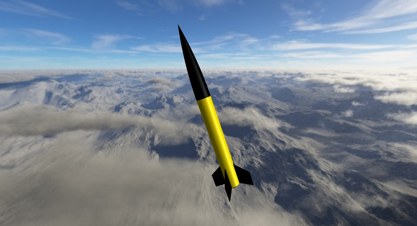
My Level 3 rocket’s design is based on Wildman’s 5 inch diameter, fiberglass upscale Estes Goblin kit. The fin shape is adjusted slightly from the kit, and carbon fiber layups will be added to the fins to increase stiffness. I created a preliminary OpenRocket model based on the product page with best guesses at mass numbers and dimensions (below).
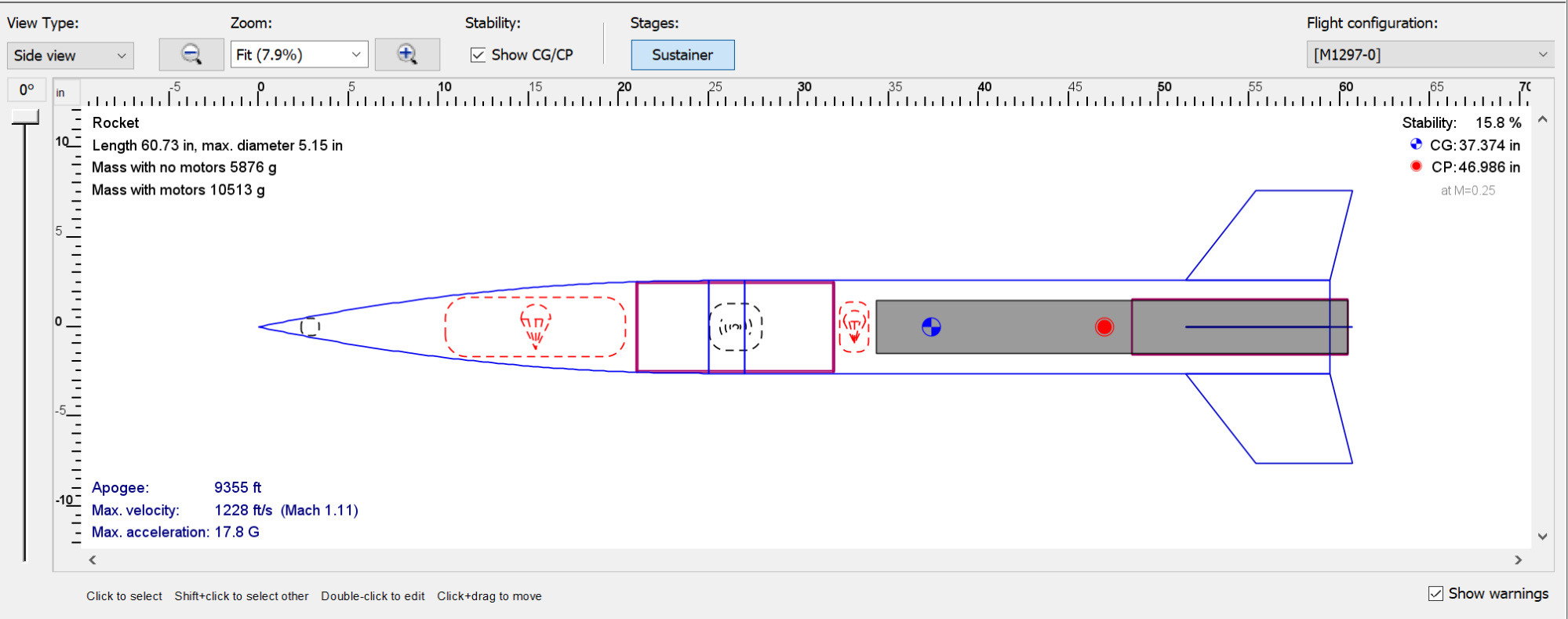
The rocket is designed to just fit a 75mm/4 propellant grain rocket motor. This is the physically smallest motor size that’s still technically an M-class, a requirement for the Level 3 certification flight. This does mean I’ve left myself ~2 inches in which I now need to fit a drogue parachute and recovery charges (which you can see just forward of the end of the grey solid rocket motor in the design above). Here are my high-level anticipated flight parameters:
| Parameter | Value |
|---|---|
| Construction | 5 in fiberglass airframe |
| Rocket length | 61 in |
| Rocket motor | AeroTech M1297-White Lighting (75mm, 4 grains) |
| Weight, wet | 10.4 kg |
| Weight, dry | 5.8 kg |
| Drag coefficient, CD | 0.54 |
| Rail exit velocity, 10ft rail | 106 ft/s |
| Maximum altitude | 9400 ft AGL |
| Maximum velocity | 1233 ft/s |
| Launch acceleration | 18 G’s |
| Launch stability | 1.55 Calibers, or 15% overall length |
| Loaded CG location | 37.6 in from tip |
| Loaded CP location | 47 in from tip |
| Drogue parachute & speed | 24in round, 80 ft/s |
| Main parachute & speed | 60in Iris (toroidal), 18 ft/s |
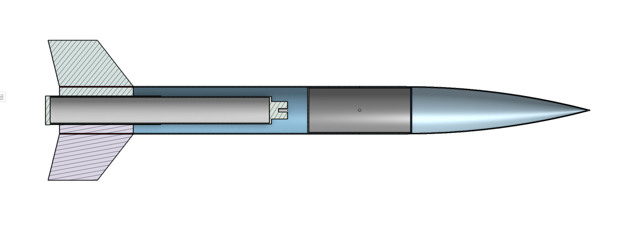
The airframe was also roughly mocked up on Onshape using a higher-fidelity model of the rocket motor using manufacturer drawings. This overall just confirms the clearance we saw using OpenRocket. The switch band may also give me 1in extra clearance between motor forward closure and electronics bay as well – we’ll know once the kit arrives.
The avionics bay (grey cylinder just forward the motor in the picture below) provides sufficient space for two redundant dual-deployment flight computers, as required by NAR for Level 3 certification flights, as well as space for additional payloads including GPS trackers to aid in recovery. Deployment will be controlled by 2 commercial/off-the-shelf (COTS) dual-deploy altimeters (probably just Stratologgers?), and will also be test-flying the new LoRa-based miniature GPS trackers designed by me during the summer of 2023.
Recovery Setup
The rocket uses a head-end dual-deployment recovery setup. A small drogue parachute in the motor section is deployed using a small black powder charge at apogee, or the highest point of the rocket’s flight, to slow its fall to ~50-100 ft/s. A larger main parachute, located in the nosecone, is deployed about 1,000 ft off the ground and reduces is speed to under 20 feet per second (15 mph). The grey avionics bay, which houses the flight computers which control paachute deployment, is in between these two parachute bays.
The avionics bay (grey, above) is a short piece of Fiberglass coupler tube that’s used to connect the nosecone to the main body of the rocket. When i’s time to deploy these two parachutes, a small, black powder charge is used to push the main rocket body or nosecone off of the electronics bay, allowing the parachute to enter the airstream and ideally deploy. (If I get really unlucky, the main parachute could get tangled inside the nosecone and never actually deploy, which probably wouldn’t be healthy for my rocket.)
This “dual-deploy” parachute deployment process is shown in the gallery below for AerospaceNU’s TRD from April 2022:
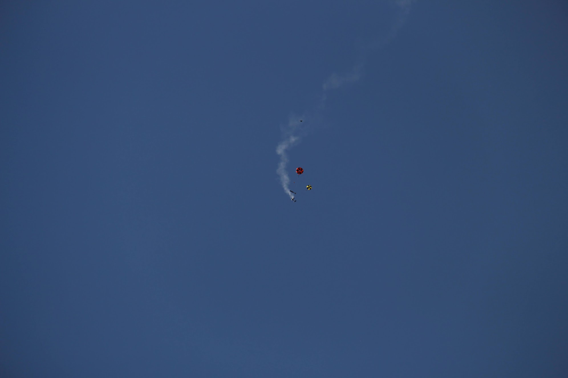
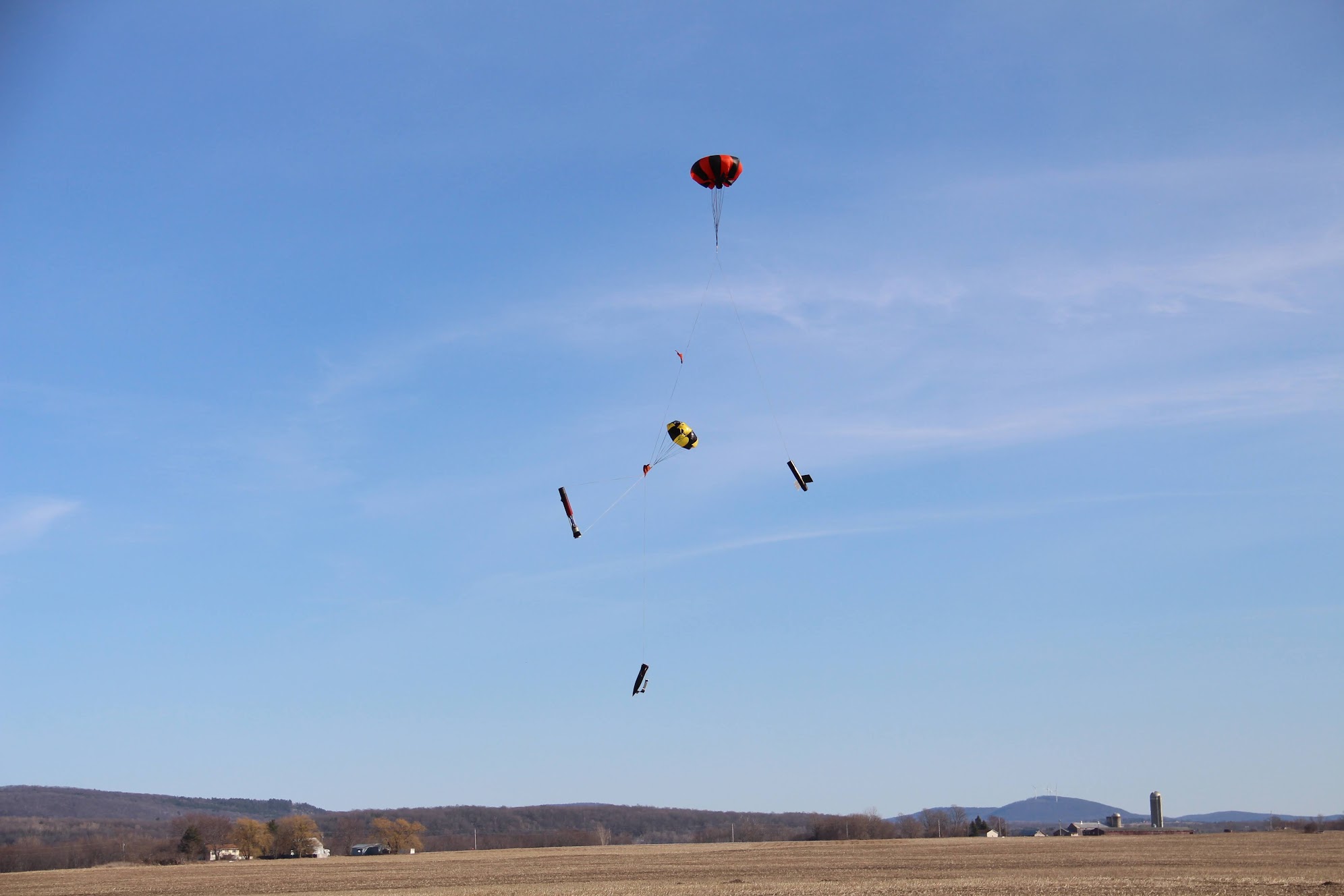
The sections of the rocket are connected to each other and to parachutes by a rope commonly called “shock cord”. This rope, which is usually made out of Kevlar (or sometimes also nylon) needs to be strong enough to take the sudden drag force that happens when the parachute inflates, as well as survive the black powder charge used to separate rocket section.
Recovery Math
I sized the drogue and main parachutes using OpenRocket. I intentionally used conservatively large mass numbers for parts, which should give me some headroom in case my model ends up heavier than I expect. The drogue parachute was sized to keep me below 90 ft/s, and the main parachute to keep me below 20 ft/s. It’s also super easy to change out parachute sizes later down the line, but it’s good to get an initial order of magnitue so we can make sure that the parachutes I’ll need will actually fit into the rocket’s parachute bay.
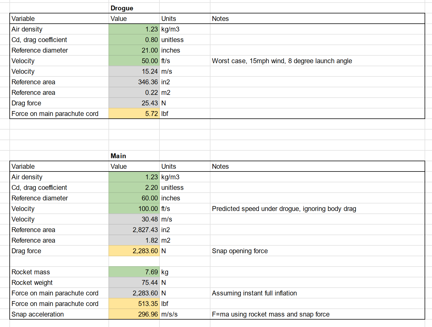
To try to get a rough order of magnitude for shock cord sizes, I calculated the force on a parachute that instantly inflated to full size at worst-case descent velocity (right). For our drogue parachute, that’s the horizontal velocity of the rocket at apogee, which is influenced by the wind speed and initial launch angle. For our main parachute, it’s a pessimistic guess at free-fall velocity.
Based on this math, I proposed just using 1/4" Wildman Kevlar cord, which is rated to 4000 lb breaking strength, for both drogue and main parachute harnesses. This should be sufficiently overkill for snap loads and withstanding dynamic deployment events.
Most high power dual-deploy rockets also use shear pins (nylon bolts, usually) to hold together rocket sections during ascent, but break when it’s time for parachutes to be deployed. To figure out what size/how many shear pins we should use, I assuemd my rocket bays would be perfectly sealed from air pressure changes as we ascend. Using the standard atmospheric model, the pressure difference between sea level and 10,000 ft altitude was determined to be 4.6 psi. Over a 5in-diameter bulkhead, this translates to a force of 90 lbf.
A common size of shear pin used in hobby rocketry is #4 (~M3 for our metric friends), which shear at approximately 40lb. I proposed using 4x 4-40 shear pins for retaining the drogue and main parachute bays against this pressure difference. Starting points for black powder deployment charge sizing (and also shear pin size/quantity estimation) will be calculated using u/maxjet’s awesome charge size calculator.