Some Basic Aerodynamics
All model rockets, not just this Level 3 rocket project, use fins or other aerodynamic control surfaces to help keep them aerodynamically stable and flying in the direction we want ’em to — up (citation needed). Going up in one piece is a pretty important part of being a model rocket. If the rocket doesn’t go where we want it to, because of aerodynamic related failures or otherwise, it would be a pretty[1] bad[2] time[3]
So it’s important to be aerodynamically stable, so your rocket goes the direction you want. But what does being stable actually mean? This pixelated NASA graphic explains that to be stable, “the center of pressure must be located below the center of gravity”. They define the Center of Gravity (CG) as the point at which you could balance the rocket horizontally on you finger, and the Center of Pressure (CP) as (somewhat hand-wave-ily) the point through which all aerodynamic forces act. I think it’s probably more intuitive to think of CG as the spot by which you could hang your rocket from the ceiling and it would balance, and the CP as the sort of average spot on which drag forces act. And as long as the “average spot where drag’s pushing on your rocket” is aft of its CG, when the rocket wiggles into the airframe, drag from the fins help push it back into the airstream.
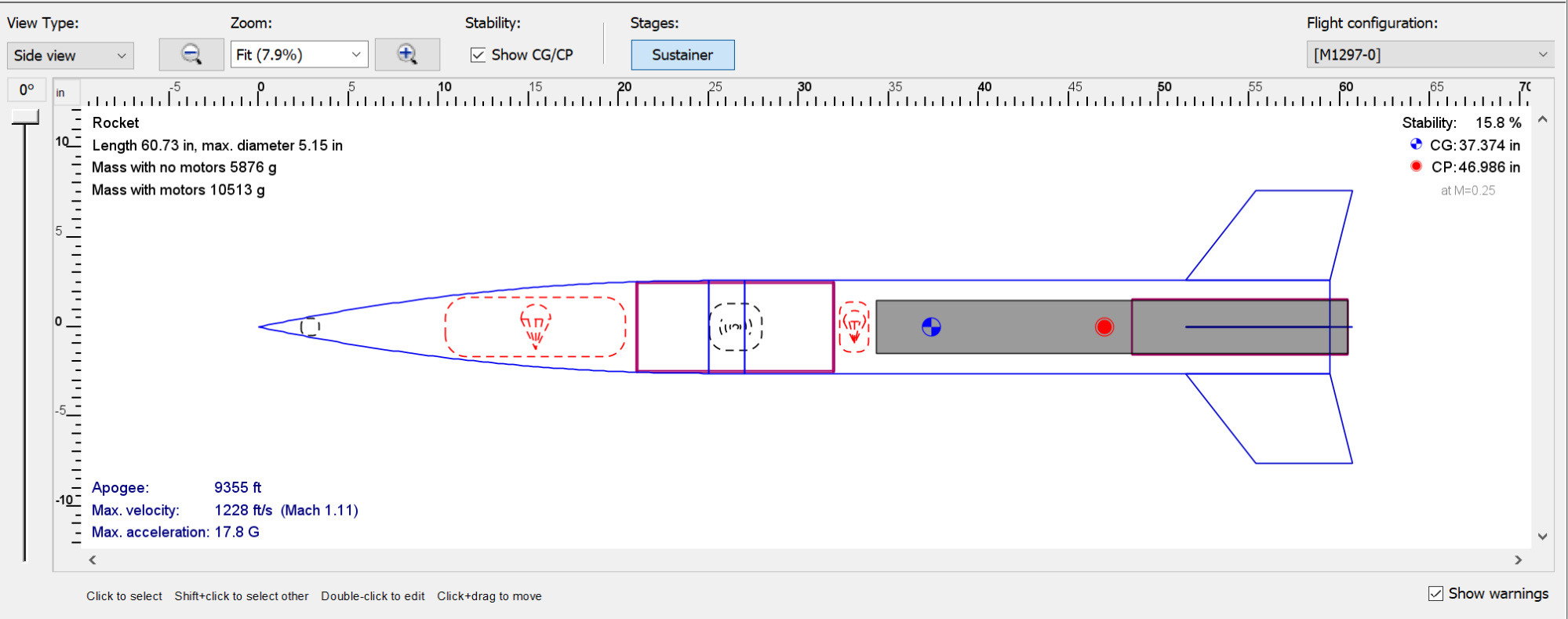
You can actually see the CG (blue cross) and CP (red dot) in my rocket’s design in OpenRocket above. I tell OpenRocket the size and material composition of my rocket’s components, and it calculates CG and CP for me. This calculation makes some simplifying assumptions to make this Center of Pressure calculation easier.
If I wanted to change the stability of my rocket, I basically have two options: I could change the mass distribution to move the Center of Gravity around, or I can grow/shrink my fin’s size to move the rocket’s CP aft/forward. I’ve both added nose weight to bring CG forwards and moved the motor mount aft, and played with the fin size a bit, in my design.
Some Simplifying Assumptions
So we stick our rocket design into OpenRocket and it tells me my CG and CP locations look good. I should be fine to send it, right?
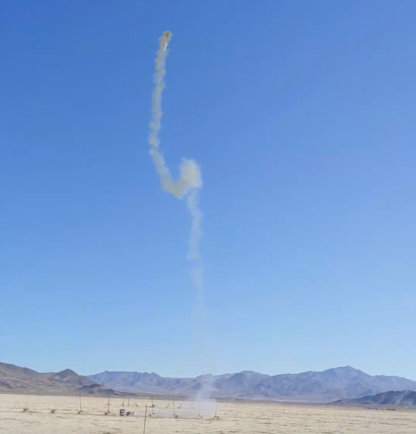
This model, which I flew at LDRS 40 in the Mojave desert in June 2022, was stable in OpenRocket. But in flight it did a loop-the-loop! What happened??
Turns out, those simplifying assumptions aren’t super valid past a couple of degrees Angle of Attack (the angle between the rocket and the oncoming airstream). As pith increases, the center of pressure tends to move forwards up a rocket, decreasing stability. And on the day I launched the rocket, with ~20 mph winds, my rocket would come off of the launch pad with as much as a 30 degree AoA. If I’d dug into OpenRocket and re-ran the simulation using that number, it would have told me my rocket was, in fact, going to become unstable!
In this particular design, I had done a few things that individually decreased stability, and together led to the rocket spinning out:
- I used only 3 fins. Fewer fins means there are some rocket angles that produce a lot lower corrective moment.
- I used marginally small fins. They were designed for a zero wind day, not a 20+ mph wind day.
- I used a “boat tail”, a tapered section at the bottom of the rocket, to reduce drag and make it go higher. But reducing the drag on the aft end of the rocket moves CP forwards, reducing stability even more.
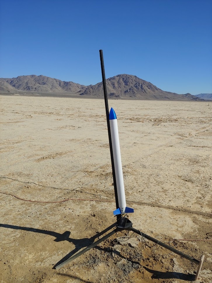
My unstable “Send-It” rocket on the pad.
So how’s this tie into this project? My biggest takeaway from this failure is that model rockets that sim stable at zero AoA might not be stable at higher AoAs. I should be simulating my designs using worst-case expected Angle of Attack numbers, not just at/near zero. This ties into a more general theme of wanting to do a better job comprehensively documenting design performance, which might have caught this (and other oversights) earlier in the design process.
Fin Flutter (and Friends)
So now we know we need fins to make our rocket go up, and figuring out how to size them is, sort of, rocket science. But fins aren’t perfectly rigid surfaces that stick into the airstream – they’re made of real materials, with finite stiffness. And on higher performance flights reaching higher speeds, this quirk of reality starts to matter more.
One fun effect that drops out of the math is the idea of fin flutter. Fin flutter is when axial vibration of the fin can be reinforced by the airflow going over it, leading to oscillations of increasing amplitude until the thing shakes itself apart. This divergent vibration can happen above a particular airspeed, dependant on fin geometry and material and things. The NACA diagram above shows a couple of different modes (ways) that this vibration might manifest in a fin. A very cool onboard video from another rocketeer demonstrating this (plus some bonus rolling shutter artifacts) is below.
It’s really hard to estimate the airspeed at which fin flutter can exist without making some assumptions, or building and fine-tuning a nonlinear model for your particular fin. Fin analysis software like AeroFinSim makes some assumptions to linearize the problem, which gives us a conservative estimate for the speed above which fin flutter can occur.
The other fun fin failure mode is divergence, a radial twisting of the fin into the airflow such that its leading edge has an angle of attack and the fin material isn’t sufficiently stiff to “pull” it back straight.
This video from a professor at Duke on YouTube, which I was sent by another rocketry friend, was a good introduction; Aeroelasticity is super cool. Note the demo towards the end, where they’re able to test a fin at over 2x the linearly predicted flutter speed. The fin does vibrate, but it’s not divergent – its oscillations are bounded. The video explains this as unmodeled nonlinear effects which mean there’s a grey area between “my fin is capable of sustaining a vibration” and “my fin will fall apart”.
Modeling with FinSim
To analyze my fins using FinSim, I trimmed down the height so they normal trapezoids instead of the cool Estes Goblin look. Initial simulations using the stock 1/8" G10 fiberglass fins that came with the kit were pretty sketchy, and showed fin flutter/divergence at just a few hundred ft/s. To get this velocity higher, we have a few different knobs we can turn, all of which fundamentally come back to increasing overall fin stiffness:
- Increase thickness
- Decrease fin height/semi-span
- Make the fin out of something stiffer
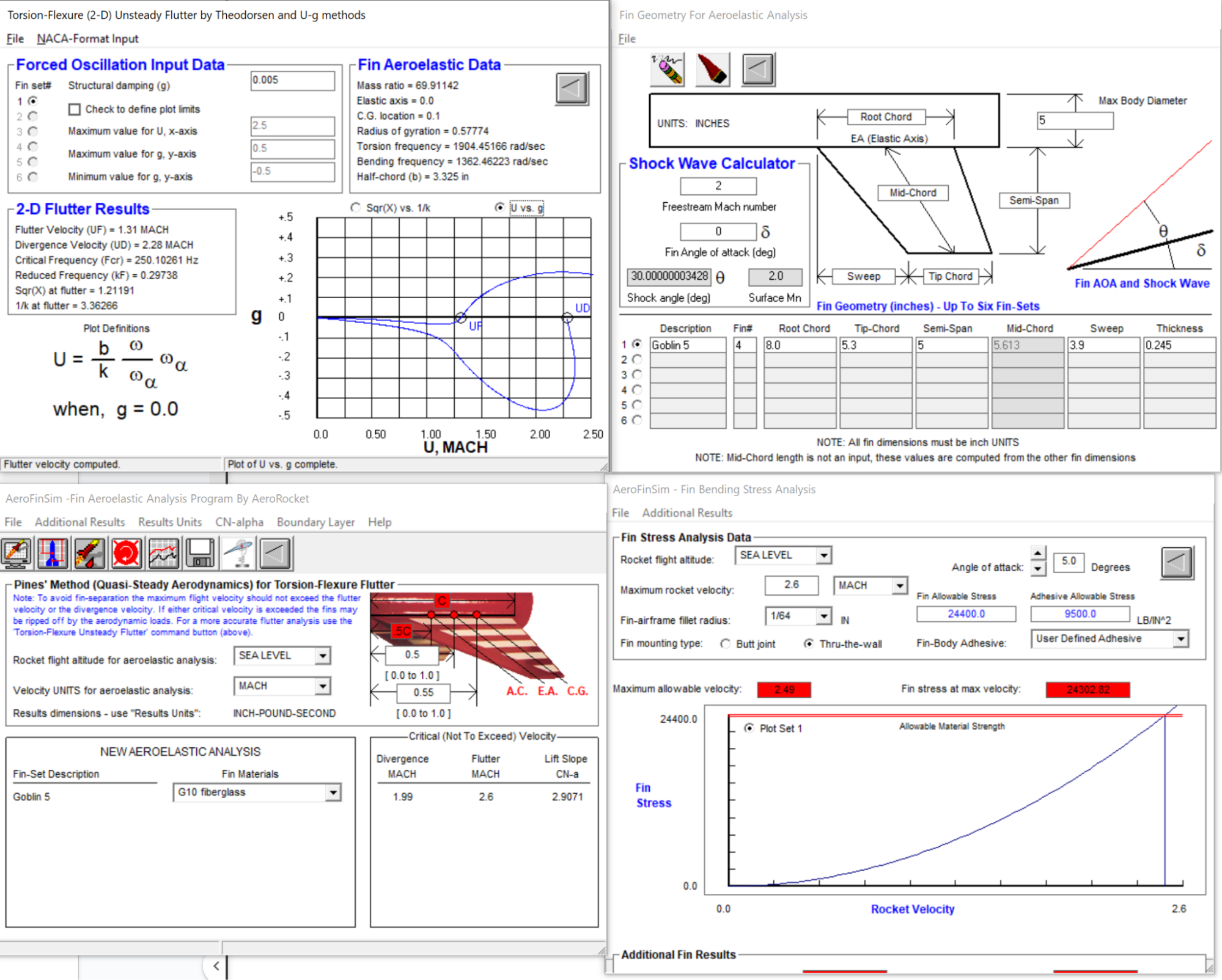
I chose to sort of do all 3, by adding 4 layers of carbon fiber on top of the G10 fiberglass fin core and reducing the fin height down to 5in. Carbon fiber is much (~10x) stiffer than G10, and adding material on top also increases stiffness. This does mean we now have to deal with simulating a composite material made of fiberglass, carbon fiber, and two different kinds of epoxy. I get around this by running FinSim simulations assuming the fin is made entirely of fiberglass or epoxy, and using that as my worst-case. This worst-case, shown in the image to the right, shows 5 layers of G10 fiberglass simulating to a flutter velocity of Mach 1.3 and divergent of Mach 2.3 at sea level. Re-running this using material properties taken from Sollar’s 3k twill + 820 resin system show a flutter of Mach 2.4 and divergence of Mach 4, which is well into overkill territory for a rocket going just barely Mach 1.
The big takeaways I have from my research and experiments with FinSim so far are:
- Fin flutter/divergence is a problem, but it’s hard to actually predict when it’ll happen
- Making your fin out of a stiffer material is helpful in increasing flutter/divergence velocities
- Stiffness is part of why we see carbon fiber parts in high-performance rockets (plus being lightweight)
- Corollary, G10 fiberglass is like a wet noodle in comparison
- Reducing fin height is also helpful
- Making your fin thicker is very helpful in increasing flutter/divergence velocities
- Stiffness probably also scales with some power of thickness, like in Mechanics with simple beans
I’m excited to dig into playing with wet carbon fiber layups as I get started building soon!